
HOME AUTOMATION USING BLUETOOTH AND PIR SENSOR ::
This Project aims to implement controlling of the appliances around us in our presence using Bluetooth and getting the work done with the less effort by us.
Automation helps us to control the devices in home, office or some other place, what could you believe that you can switch on a tv, turn on an ac from the place you are present using a device in your hand...!!!
Automation helps us to control the devices in home, office or some other place, what could you believe that you can switch on a tv, turn on an ac from the place you are present using a device in your hand...!!!
Use of PIR(passive infra red sensor) senses our presence illuminates the room and activate the bluetooth device and by which the appliances can be controlled. PIR is used here to save the power by making the bluetooth receiver in sleep mode when ever it is not used.

Working of devices ::
Passive Infra Red:: PIR is a device which recognizes the active human presence. Then pir sensor give the logic high to the micro controller indicating the presence of a human


Block Diagram:
Working of devices ::
Passive Infra Red:: PIR is a device which recognizes the active human presence. Then pir sensor give the logic high to the micro controller indicating the presence of a human
The 3 pins to the PIR are one for giving the power supply, one for the ground and other is the output pin connected to any one pin of the ports of micro controller which indicates the presence of a person. As long as there is no person detected then the sensor give logic 0 to the micro controller, when there is a active human presence then the logic high is sent to the micro controller indicating that a person has entered the room.
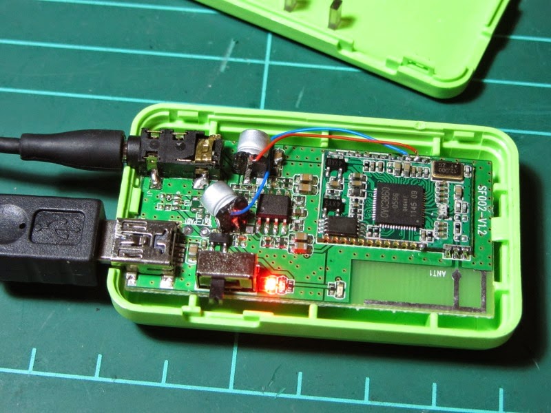
Bluetooth receiver::
As any one know the application of bluetooth is to exchange the data, similarly here we use the bluetooth receiver module to receive the data which we have sent to the automation device in order to indicate the micro controller what operation has to be done.
For this purpose the bluetooth module is connected serially to the micro controller using serial communication channel and the out of serial communication is connected to any pone pins of the ports of the micro controller, the logic of which device to turn on and which device to turn off is written in the programming part, and the bluetooth device becomes active only when the PIR sensor detects a person(in our project), till the person is not detected the receiver is in power down mode, once the sensor senses a person the device turn on and will be waiting for the input from the user.
Relay Switch:
Relay switch is used to connect the appliances to the micro controller output pins as the home appliances work on 220v ac power supply. As we cannot connect 220v power supply directly to the micro controller we use a relay switch.
The function of the relay switch is that when ever the output from the micro controller is high then the connection of the 220v is given to the appliances and when the out of the MC is logic low then the switch is connected to the ground. This avoids the problem of connecting the high voltage working devices to the micro controller.
Working of the project ::
Intially all the pins of the micro controller will be in logic high position, once we connect peripherals to the MC then all the pins are made logic low to implement the logic. Initially the output of the PIR pin is logic low when there is no presence of the person, once the person is detected the bulb of the room turn on at the same time activating the bluetooth receiver. once the bluetooth is turned on then it waits for the command from the user from his electronic device containing bluetooth controller app. From that app when a particular button is pressed then it is sensed and is detected by the bluetooth device and based on the logic written on the micro controller the device is turned on and can be turned off.
Circuit:
POWER SUPPLY::
Supply to the micro controller is given via transformer which gives 15v ac output with 500mA current, then the output of the transformer is connected to the bridge rectifier which give constant 5v dc output which is given to the micro controller.
logic implementation :: (using keil uvision software)
#include
sbit pir= P^1.0;
sbit bluetooth = P2^5;
sbit device1= P0^1;//device 1 to pin 0.1
sbit device2= P0^2;//device 2 to pin 0.2
sbit device3=P0^3;//device 3 to pin 0.3
void main()
{
int i;
wihle(1)
if(pir==1)//person detected
{
device1=1;//light on
tcon=0x20;
scon=0x50;
device1=0;
device2=0;
device3=0;
if(RI==0);
{
i=sbuf;
if(i==1)
device1=0;
elseif(i==2)
device2=1;
elseif(i==3)
device2=0;
elseif(i==4)
device3=1;
elseif(i==5)
device3=0;
}
else
{
device1=0;
device2=0;
device3=0;
}
}
}